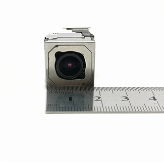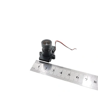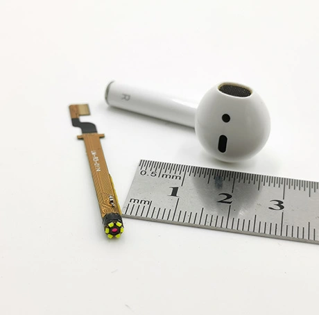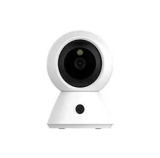
Choosing a USB camera module for an endoscope or cavity inspection device involves more than finding the smallest available camera board. The module must fit inside the enclosure, focus clearly at the required distance, provide sufficient field of view, operate under limited illumination and maintain a reliable USB connection through the complete cable assembly.
A camera that produces a clear image during an open-bench test may perform differently after it is installed behind a protective window, placed next to an LED, connected through a long cable or inserted into a reflective cavity. Mechanical, optical, electrical and software requirements should therefore be evaluated as one complete imaging system.
An endoscope camera module is a compact imaging assembly designed to capture video or still images inside a narrow, enclosed or difficult-to-access space.
This design checklist explains the main factors engineers and purchasing teams should confirm when selecting a small USB camera module for endoscope inspection, industrial borescopes, pipe inspection tools, equipment-maintenance cameras and other cavity imaging devices.
1. Define the Endoscope or Cavity Inspection Application
Application definition is the process of identifying what the camera must observe, where it will be installed and what image information the operator or software must obtain.
Endoscope and cavity inspection systems can serve very different purposes. Some devices only need to provide a live view for navigation, while others must identify scratches, contamination, corrosion, text, component damage or assembly defects.
Before comparing camera modules, define the inspection objective:
Is the camera used for general visual observation or detailed defect inspection?
What is the smallest feature that must be visible?
Will a person view the image, or will software analyze it?
Is the camera stationary, handheld or moving through the cavity?
Is the target surface flat, curved, reflective or textured?
Will the system be used in a dry, dusty, oily, humid or liquid environment?
Does the operator need real-time video, still-image capture or both?
A 0.3MP camera may be sufficient for basic navigation and presence detection, but it may not provide enough pixels for recognizing small text or measuring fine defects. Higher-resolution USB camera module options should be evaluated when the inspection requires additional visible detail or digital cropping.
The operating environment must also be defined early. A module intended for a dry industrial cavity has different enclosure, sealing and material requirements from a camera installed in a washable probe or regulated medical device.
2. Confirm the Available Mechanical Space
Mechanical compatibility means that the camera, lens, cable and mounting structure fit inside the complete device without blocking the image or placing damaging stress on the components.
Do not evaluate camera size only by looking at the PCB width. The complete installed assembly can include:
Rigid PCB or flexible FPC
Image sensor and supporting components
Lens and lens holder
USB bridge or processing components
Cable soldering area or connector
Cable bend radius
Mounting holes or adhesive area
Protective enclosure and front window
LED or other illumination components
Measure the maximum available width, length, thickness and total optical height inside the enclosure. The measurement should include production tolerances and enough clearance for assembly.
| Mechanical Item | Information to Confirm | Common Design Risk |
|---|---|---|
| Probe or enclosure diameter | Minimum internal diameter at the camera position | The PCB fits, but the lens holder or LEDs do not |
| Available module length | Distance available for the lens, PCB and cable joint | The cable exit increases the required installation length |
| Lens opening | Diameter and location of the enclosure aperture | The enclosure blocks part of the field of view |
| Cable direction | Rear, side or angled cable routing | Repeated bending damages the cable or solder joint |
| Mounting method | Screws, bracket, adhesive or enclosure compression | Mechanical pressure tilts the optical axis |
| Front window | Material, thickness, coating and lens-to-window spacing | Reflections, contamination or focus changes reduce clarity |
A custom PCB or FPC can help fit the electronics around a narrow mechanical structure. However, changing the board shape may affect component placement, electromagnetic performance, heat distribution, manufacturing yield and test procedures. The camera supplier should review the complete enclosure drawing rather than only a requested board width.
3. Match the Lens to Working Distance and Field of View
Lens selection determines how much of the cavity is visible, where the image is focused and how accurately the scene geometry is reproduced.
Three optical requirements should be specified together:
Working distance: the distance from the front of the lens to the target.
Field of view: the physical width and height visible at that distance.
Smallest visible feature: the minimum object, defect or character that must be recognized.
A wide-angle lens can show more of the cavity at a short distance, but it may introduce greater barrel distortion and distribute the available pixels across a larger area. A narrower lens provides more pixels on a smaller target area but may not capture enough of the surrounding structure.
For close inspection, the standard focus setting may need to be changed to a macro-focus configuration. Do not assume that a camera focused from several centimeters to infinity will automatically produce a sharp image when the target is only a few millimeters away.
Optical Questions to Answer
What are the minimum, typical and maximum target distances?
What physical target width and height must be visible?
Must the complete circular cavity fit inside the image?
How much lens distortion is acceptable?
Does the target surface have different depth levels?
Will the camera move toward and away from the target?
Is edge sharpness as important as center sharpness?
Will a cover glass or protective window be installed?
The lens should be tested in the final housing. A recessed lens may capture the inner wall of the enclosure, while an LED positioned too close to the lens can create flare or bright reflections.
4. Design the Illumination System
An endoscope illumination system provides enough controlled light for the camera to reproduce useful detail inside a dark or enclosed space.
Cavities often have little or no ambient light. Image quality therefore depends on the camera and illumination system working together.
Common illumination options include:
Visible white LEDs for natural-color inspection
Infrared LEDs for applications that do not require visible color
External fiber-optic illumination
Ring-shaped LEDs around the camera lens
Side illumination for emphasizing surface texture
More light does not always produce a better image. Strong direct illumination can create reflections on metal, liquid, plastic or glossy surfaces. Uneven lighting can make one part of the image overexposed while another part remains too dark.
Illumination Design Checklist
Confirm the required light wavelength and target color response.
Evaluate LED position relative to the lens.
Prevent the enclosure wall from reflecting light into the lens.
Check brightness at the minimum and maximum working distances.
Evaluate glare on wet, metallic or polished surfaces.
Confirm whether LED brightness must be adjustable.
Measure temperature after continuous operation.
Test image noise and motion blur under the final illumination level.
When the target includes reflective surfaces, a lower exposure combined with controlled light positioning may produce better results than simply increasing LED power. Diffusers, polarizers or alternative illumination angles can also be evaluated where the mechanical design allows them.
5. Select the Required Resolution and Frame Rate
Camera resolution determines how many image pixels are available, while frame rate determines how frequently a new image is captured and transmitted.
The highest available resolution is not automatically the best selection. Higher resolution can increase bandwidth, processing requirements, storage needs and system cost.
Resolution should be selected according to:
The physical field of view
The smallest feature that must be visible
The expected viewing-screen size
Whether digital zoom or image cropping is required
Whether software performs detection, recognition or measurement
The available USB bandwidth and host processing capacity
CK Vision’s compact CK-EDP-0.3-V2.0 configuration uses a GC030A sensor, an M4 lens and USB 2.0 UVC output, providing up to 640 × 480 video at 30 fps in MJPEG format. This type of configuration can provide a compact starting point for basic visual inspection, navigation and embedded camera development.
A higher-resolution camera may be more suitable when the operator must identify fine cracks, small labels, surface contamination or other detailed features across a relatively large field of view.
Frame rate should be evaluated according to movement. A slowly positioned inspection camera may not require an extremely high frame rate, while a moving probe, rotating component or robotic inspection system may need smoother video and shorter exposure times.
6. Verify USB Interface and Cable Reliability
USB integration includes the camera electronics, video format, cable, connector, host controller, operating system and application software.
UVC-compatible USB cameras can simplify integration because supported operating systems can recognize them as standard video devices. However, reliable operation still depends on the complete host environment.
Confirm the following items:
USB 2.0 or USB 3.0 interface requirement
MJPEG, YUYV or other required output format
Required resolution and frame-rate combinations
Host operating system and processor platform
USB OTG and UVC support for Android devices
Connector type and orientation
Total cable length
Cable flexibility and bend life
Shielding and electromagnetic environment
Available USB power
A long or thin cable can affect voltage, signal quality and connection stability. This is particularly important for flexible endoscopes and pipe inspection tools, where the camera may be positioned far from the host device.
Do not validate the camera with a short laboratory cable if the production device will use a substantially longer cable. Test the actual camera, cable, connector, host and software together.
Android compatibility should also be checked on the target device. The presence of a USB connector alone does not confirm that the host supports USB OTG, UVC video, the selected image format and sufficient camera power.
7. Evaluate Power Consumption and Thermal Design
Thermal design controls how heat generated by the camera, illumination and surrounding electronics is managed inside the enclosure.
Small endoscope and cavity inspection devices often have limited airflow and little space for heat spreading. The complete thermal load can include:
Image sensor
USB bridge or processor
Voltage regulators
LED illumination
Other electronics inside the probe
Low camera power can help reduce heat generation, but it does not by itself prove that the complete device is safe for a medical or temperature-sensitive application. Thermal performance must be measured after the camera and LEDs are installed in the final enclosure.
Testing should cover:
Continuous operating temperature
Maximum LED brightness
Highest expected ambient temperature
Enclosure material and wall thickness
Image noise after prolonged operation
Focus stability as temperature changes
8. Plan for Environmental Protection
Environmental protection prevents dust, moisture, oil, cleaning agents or mechanical stress from reducing camera performance or damaging the device.
The bare camera module should not be assumed to provide the same environmental protection as the complete inspection device. The enclosure designer is normally responsible for sealing and protecting the final assembly.
Depending on the application, confirm:
Expected operating and storage temperature
Humidity and condensation risk
Dust, oil or chemical exposure
Water or liquid contact
Cleaning and disinfection methods
Vibration, shock and cable pulling force
Lens-window scratch resistance
Required enclosure ingress-protection level
For liquid or washable environments, sealing should be validated at the complete device level. Adhesive selection, cable entry, front-window bonding and material compatibility may be as important as the camera module itself.
9. Separate Industrial Inspection from Medical Compliance
Medical-device suitability depends on the complete device design, intended use, risk classification, materials, manufacturing controls and applicable regulatory requirements.
A compact USB camera module may be considered during the development of medical imaging equipment, but the camera module alone should not automatically be described as a certified medical device.
Medical-device developers may need to evaluate:
Electrical safety and electromagnetic compatibility
Biocompatibility of patient-contacting materials
Cleaning, disinfection or sterilization processes
Risk management and software validation
Traceability and production-quality controls
Country-specific regulatory requirements
These requirements apply to the completed device and must be determined by the medical-device manufacturer and its qualified regulatory team.
Industrial borescopes, pipe inspection tools and maintenance cameras may not require medical-device compliance, but they can still need environmental, electrical and quality testing appropriate to their intended operating conditions.
10. Build and Test a Representative Prototype
A representative prototype uses the intended camera, lens, cable, illumination, enclosure and host system to reproduce the expected production conditions.
A useful prototype test should not evaluate only whether an image appears. It should verify whether the complete system meets the application requirements.
Prototype Validation Checklist
Confirm that the camera fits inside the enclosure.
Check focus at the minimum, typical and maximum working distances.
Measure the physical field of view.
Confirm that the smallest required feature is visible.
Inspect edge sharpness and lens distortion.
Test reflections from the front window and enclosure.
Evaluate lighting uniformity and LED adjustment.
Run the camera through the full production cable length.
Test all required resolutions and frame rates.
Confirm compatibility with the target operating system and software.
Measure temperature during continuous operation.
Test image stability under expected movement and vibration.
When exposure, white balance, color, sharpness or noise reduction requires additional adjustment, camera ISP tuning services can be evaluated for the selected sensor, lens, illumination and application environment.
Engineering samples should be approved before the project moves into tooling or mass production. Changes to the lens, enclosure window, LED position or cable after sample approval may require the optical and image-quality tests to be repeated.
Endoscope Camera Module Design Checklist
An endoscope camera design checklist records the mechanical, optical, electrical, environmental and commercial information required to evaluate a custom camera configuration.
| Design Category | Information Required | Why It Matters |
|---|---|---|
| Application | Inspection target and required result | Determines resolution, optics and image-quality priorities |
| Installation space | Maximum width, length, thickness and probe diameter | Determines PCB, FPC, lens and cable structure |
| Working distance | Minimum, typical and maximum target distance | Determines lens focus configuration |
| Target coverage | Required visible width and height | Determines field of view and focal length |
| Visible detail | Smallest defect, object or character | Helps determine resolution requirements |
| Illumination | Visible, infrared or external light source | Affects exposure, color and reflection control |
| Host platform | Operating system, processor and USB interface | Determines compatibility and video output requirements |
| Cable | Length, flexibility, connector and exit direction | Affects signal stability and mechanical reliability |
| Environment | Temperature, moisture, dust, chemicals and vibration | Determines enclosure and validation requirements |
| Customization | PCB/FPC, lens, firmware, LED and image tuning | Defines engineering scope and prototype requirements |
| Project quantity | Sample quantity and estimated production demand | Supports technical and manufacturing evaluation |
Customers who have not yet completed these requirements can review the small USB camera module selection guide before requesting a custom sample.
Frequently Asked Questions
What camera resolution is suitable for an endoscope?
The required resolution depends on the field of view and the smallest feature that must be recognized. A 0.3MP camera may support general observation and navigation, while detailed defect inspection, text recognition or digital cropping may require a higher resolution.
Can a USB camera module focus at a very short distance?
Yes, but the lens must be selected and focused for the required target distance. A standard fixed-focus configuration intended for medium or long distances may not produce a clear close-range image.
Can the PCB or FPC be customized for a narrow probe?
The PCB or FPC outline, component arrangement, cable position and mounting structure can often be evaluated for customization. The final design depends on the available space, electrical layout and production requirements.
Does an endoscope USB camera require a separate driver?
A UVC-compatible USB camera can normally use the standard UVC support available in a compatible operating system. However, the target host, USB controller, video format and application software should still be tested together.
How can reflections inside a cavity be reduced?
Reflections can be reduced by adjusting LED position and brightness, changing the lighting angle, using a diffuser, selecting a suitable front-window material or modifying exposure parameters. The correct solution depends on the target surface and enclosure design.
Can the same camera be used for medical and industrial endoscopes?
The same camera architecture may be evaluated for different imaging projects, but medical-device development involves additional regulatory, safety, material and production-control requirements. Suitability must be verified at the complete device level.
What information is needed to request a custom sample?
Provide the available camera dimensions, target working distance, required field of view, smallest visible feature, illumination conditions, host system, cable length, connector type and expected project quantity. An enclosure drawing and sample target images are also useful.
Conclusion
A successful endoscope or cavity inspection camera must balance mechanical size, working distance, field of view, resolution, illumination, cable reliability and environmental protection. Selecting the smallest camera board without evaluating the complete imaging system can lead to poor focus, blocked viewing angles, unstable USB transmission or excessive reflections.
For a custom evaluation, send CK Vision your enclosure drawing, probe dimensions, target distance, required image coverage, lighting conditions, host platform and cable requirements. The engineering team can then evaluate the appropriate camera structure, lens, PCB or FPC, video output and image-quality configuration.