Adding a camera to an embedded product is rarely as simple as selecting a resolution and connecting a USB cable. The camera module must fit within the available enclosure, focus clearly at the required working distance, communicate reliably with the host system, operate within the available power budget and produce stable images under the actual lighting conditions.
These requirements become more challenging in endoscopes, handheld inspection tools, compact robots, smart terminals and portable IoT devices. A camera that performs well on a development bench may still fail after it is installed inside a narrow enclosure, connected through a longer cable or exposed to changing illumination.
This guide explains the main factors engineers and purchasing teams should evaluate when selecting a miniature USB camera module for an embedded imaging project.
What Makes a USB Camera Module Suitable for Embedded Devices?
A suitable embedded camera is not necessarily the module with the highest resolution. The correct solution is the one that balances mechanical size, image quality, interface compatibility, power consumption, optics and project cost.
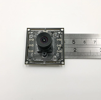
For applications where installation space is the first constraint, CK Vision’s small USB camera module for embedded devices provides a compact starting point. The CK-EDP-0.3-V2.0 uses a 0.3MP GC030A image sensor, an M4 lens and USB 2.0 output, delivering 640 × 480 video at up to 30 fps in MJPEG format. Its PCB or FPC structure, cable, connector, lens and working distance can be evaluated according to the target device.
Before selecting this or any other module, the development team should define the complete imaging requirement rather than focusing on a single specification.
1. Start with the Available Installation Space
Mechanical compatibility should be confirmed before resolution, frame rate or image-processing features. Measure the maximum available width, height and thickness inside the product enclosure. The measurement should include not only the PCB but also the lens holder, connector, cable bend radius and mounting clearance.
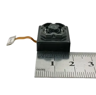
A module may appear small in a product photograph but still be unsuitable if the connector faces the wrong direction or if the cable cannot bend safely inside the housing. For narrow devices, a custom FPC structure may be more practical than a conventional rigid rectangular PCB.
| Mechanical Requirement | Recommended Configuration | Information to Confirm |
|---|---|---|
| Extremely narrow enclosure | Custom narrow PCB or flexible FPC | Maximum width, thickness and cable direction |
| Low-profile optical structure | Mini lens with a short total track length | Maximum lens height above the PCB |
| Curved or irregular internal space | Custom-shaped FPC and relocated connector | Enclosure drawing and folding direction |
| Limited mounting clearance | Customized mounting holes or adhesive installation | Fixing method and enclosure tolerance |
Providing a 2D or 3D enclosure drawing at the beginning of the project allows the camera manufacturer to evaluate whether a standard module can be used or whether a customized PCB/FPC design is required.
2. Select the Resolution According to the Actual Imaging Task
Higher resolution is useful only when the application can benefit from the additional image detail. It also increases bandwidth, processing load, storage demand and, in some cases, module size and power consumption.
A 0.3MP camera with 640 × 480 output may be sufficient for navigation, basic monitoring, object presence detection and real-time viewing inside a compact device. It is not intended for applications that require detailed text recognition, precise defect measurement or large digital zoom.
| Resolution Level | Typical Use | Main Consideration |
|---|---|---|
| 0.3MP / 640 × 480 | Basic monitoring, compact endoscope prototypes, navigation and presence detection | Small footprint and lower data requirements |
| 2MP / 1080p | Robotics, smart terminals, general inspection and video communication | Balance between detail, bandwidth and cost |
| 5MP | Surface inspection, document imaging, microscopy and detailed IoT monitoring | Higher detail with increased processing requirements |
| 4K | High-detail industrial inspection, large-area monitoring and digital cropping | Higher bandwidth, storage and host-processing demand |
Projects requiring clearer text, surface detail or image enlargement can consider a 5MP USB camera module. Applications requiring 3840 × 2160 video and greater detail can evaluate a 4K USB camera module.
3. Match the Lens to the Working Distance
Resolution alone does not determine whether the image will be clear. The lens must be focused for the actual distance between the camera and the target.
A standard fixed-focus module may be configured for objects several centimeters away or for distant viewing. However, endoscopes, pipe-inspection tools and compact measurement devices may need clear images at only a few millimeters or centimeters.
Before choosing a lens, confirm:
The minimum and maximum working distance;
The size of the object that must appear in the image;
The required depth of field;
Whether the target remains stationary or changes distance;
Whether autofocus is necessary;
Whether a protective window will be installed in front of the lens.
For a fixed-distance application, a customized fixed-focus lens is often simpler, smaller and more stable than an autofocus system. The working distance should be tested after the camera is installed behind the final enclosure window because the window material and distance from the lens can affect focus and image quality.
4. Determine the Required Field of View
The field of view determines how much of the scene the camera can capture. A wider-angle lens can show more of a pipe, cavity or room, but it may introduce greater optical distortion and reduce the number of pixels available for each object.
| Application Requirement | Lens Direction | Potential Trade-Off |
|---|---|---|
| View a wider cavity or pipe wall | Wide-angle lens | Higher edge distortion |
| Inspect a small target in greater detail | Narrower field of view | Smaller visible area |
| General embedded monitoring | Medium field of view | Balanced coverage and detail |
| Dimensional measurement | Low-distortion lens | May require a larger optical structure |
The field of view should be specified together with the sensor size, target distance and required visible area. Requesting only a lens angle without providing the installation distance may result in an unsuitable configuration.
5. Confirm USB and Host-System Compatibility
UVC, or USB Video Class, allows many USB camera modules to communicate with a host device through standard video drivers. This can simplify development on Windows, Linux and other systems that support UVC.
However, UVC compatibility does not automatically guarantee that every camera will work with every host. The development team should validate:
Whether the host operating system supports UVC;
Whether the USB port provides sufficient power;
Whether the host supports the selected resolution and video format;
Whether the application software can access camera controls;
Whether Android hardware supports USB OTG and external UVC cameras;
Whether the required cable length maintains reliable data transmission.
For Linux development, the module should be tested with the target kernel, V4L2 pipeline and final application software. For Android devices, testing must be completed on the actual tablet, terminal or embedded board because USB support can vary between hardware models and system builds.
6. Choose the Appropriate Video Output Format
USB camera modules commonly output MJPEG or YUYV video. The best format depends on the available USB bandwidth and host-processing capability.
| Output Format | Advantages | Considerations |
|---|---|---|
| MJPEG | Compressed data reduces USB bandwidth requirements | The host must decode the compressed frames |
| YUYV / YUV2 | Uncompressed output can simplify certain image-processing workflows | Requires significantly more USB bandwidth |
For compact monitoring products using USB 2.0, MJPEG is often practical because it enables higher resolution or frame rate within the available bandwidth. YUYV may be preferred when the host needs uncompressed image data and has sufficient transmission capacity.
7. Evaluate Lighting and Low-Light Performance
Image quality should be evaluated under the actual lighting conditions of the final device. A camera that looks clear in a bright office may produce noise, motion blur or unstable color inside a dark pipe, closed enclosure or industrial machine.
For low-light applications, consider the complete optical system:
Sensor sensitivity and pixel size;
Lens aperture;
Exposure time and gain;
Available LED or IR illumination;
Distance and angle between the light and the target;
Reflections from the enclosure or protective window;
Heat generated by the illumination system.
Increasing exposure time can brighten an image but may create motion blur. Increasing gain can make the image brighter but may also increase noise. A practical solution normally requires coordination between the sensor, lens, illumination and image parameters.
8. Consider Cable Length, Power and Signal Integrity
Long USB cables can introduce voltage drop, electromagnetic interference and transmission instability. The risk increases when the camera operates at higher resolution, higher frame rate or through an unshielded cable inside an electrically noisy device.
If the application requires a longer cable, confirm:
The total cable length;
The cable route inside the device;
The connector type and orientation;
Whether shielding is required;
The available voltage at the camera end;
The required resolution and frame rate;
Nearby motors, power supplies or wireless components.
The final cable configuration should be tested inside the complete device rather than only with the module connected directly to a computer.
Recommended Configurations for Common Embedded Applications
| Application Requirement | Recommended Camera Configuration | Key Validation Item |
|---|---|---|
| Very limited enclosure space | Custom PCB/FPC with an M4 mini lens | Overall dimensions and cable bend radius |
| Close-range endoscope imaging | Customized macro working distance | Focus and depth of field at the target distance |
| Pipe or cavity inspection | Wide-angle lens with optional LED illumination | Coverage, distortion and reflection |
| Battery-powered IoT device | Low-power camera with controlled frame rate | Power consumption and thermal performance |
| Windows or Linux terminal | UVC-compliant USB output | Driver, application and video-format support |
| Android embedded system | UVC camera with OTG validation | Host compatibility and available USB power |
| Detailed surface inspection | 2MP or 5MP sensor with suitable optics | Pixels on target and focus accuracy |
| High-detail digital cropping | 5MP or 4K USB camera module | Bandwidth, processing and storage capacity |
A Practical Camera Module Selection Process
Define the imaging task. Specify what the camera must detect, monitor, record or measure.
Confirm the mechanical envelope. Provide the maximum PCB, lens and cable dimensions.
Set the optical requirements. Define the working distance, field of view, target size and lighting.
Select the interface and output. Confirm the host platform, USB version, video format, resolution and frame rate.
Build and test samples. Evaluate image quality, focus, temperature, cable stability and software compatibility in the actual device.
Freeze the production specification. Confirm the approved sensor, lens, PCB/FPC, connector, cable, firmware and quality criteria before mass production.
Information to Provide When Requesting a Custom Camera Module
To receive an accurate recommendation, prepare the following project information:
Available installation dimensions;
Target application and operating environment;
Required resolution and frame rate;
Minimum and maximum working distance;
Required horizontal or diagonal field of view;
Host operating system and hardware platform;
Preferred output format;
Required cable length and connector;
Lighting or infrared requirements;
Operating temperature range;
Prototype quantity and estimated annual volume;
Target schedule for samples and production.
Common Mistakes When Selecting a Miniature USB Camera
Choosing the Highest Resolution Without Checking the Host
A high-resolution camera may exceed the USB bandwidth, processing capability or storage capacity of the embedded system. Select a resolution that matches the actual task and host resources.
Ignoring the Final Enclosure
Testing an exposed camera board does not represent performance inside the finished product. The enclosure can affect focus, illumination, temperature, cable routing and electromagnetic compatibility.
Using a Standard Focus for a Close-Range Application
A lens focused from 10 cm to infinity may not produce clear images at a few millimeters. Close-range inspection normally requires a customized working distance.
Assuming All Android Devices Support UVC Cameras
Android compatibility depends on the hardware, OTG support, USB power and system software. Always test the module with the final host device.
Confirming the PCB Size but Forgetting the Lens and Cable
The complete camera assembly includes the PCB or FPC, lens, connector and cable bend area. All of these components must fit inside the enclosure.
Frequently Asked Questions
What is a small USB camera module?
A small USB camera module is a compact imaging board that combines an image sensor, lens, processing circuitry and USB output. It is designed for integration into products such as embedded terminals, inspection tools, robots, endoscope prototypes and IoT devices.
Is 0.3MP resolution sufficient for an embedded camera?
It can be sufficient for basic monitoring, navigation, object presence detection and applications where compact size and real-time viewing are more important than fine detail. Text recognition, precision inspection and digital zoom normally require a higher-resolution camera.
Can the PCB or FPC shape be customized?
Yes. The board shape, connector position, cable direction and FPC structure can be evaluated according to the available enclosure space. A mechanical drawing should be provided before the design is confirmed.
Can the working distance be customized for endoscope imaging?
Yes. The lens focus can be configured for the required target distance, subject to lens availability and optical validation. Provide the minimum and maximum working distance, required field of view and target size.
Does a UVC USB camera require a special driver?
Many UVC-compatible host systems can recognize the camera through a standard video driver. However, compatibility should still be tested with the final operating system, hardware platform and application software.
Can a longer USB cable be used?
A longer cable may be possible, but signal integrity, voltage drop, shielding, resolution and frame rate must be evaluated. The complete cable configuration should be tested in the final device.
When should I choose a 5MP or 4K camera instead?
Choose a higher-resolution module when the application requires detailed surface inspection, small-text capture, digital zoom, image cropping or a larger number of pixels on the target. Confirm that the host can support the required bandwidth and processing load.
Conclusion
Selecting a miniature USB camera module requires more than comparing resolution specifications. Mechanical dimensions, working distance, field of view, lighting, USB compatibility, cable length and host performance must be considered as one complete imaging system.
For a faster engineering evaluation, send CK Vision your enclosure drawing, target working distance, required field of view, host platform, cable length and expected resolution. The engineering team can then evaluate whether a standard compact USB camera module is suitable or whether the PCB/FPC, lens, connector and image parameters should be customized.