Engineering Design Guide
A reliable motorcycle night vision camera system is not determined by sensor resolution alone. Camera position, lens field of view, low-light sensitivity, exposure control, video transmission, display processing, sealing, power design and vibration all affect what the rider ultimately sees.
This engineering guide explains how to define and validate those elements as a complete signal chain. It is intended for OEM developers evaluating an embedded motorcycle camera system, rather than consumers choosing an aftermarket action camera.
Start With the Complete Night-Vision Signal Chain
A camera that performs well on a laboratory bench may produce a poor rider-facing image after installation. The complete system should therefore be treated as a chain in which every component can limit image quality or increase latency.
Selecting a low-light image sensor is only the beginning. The lens must deliver sufficient light, the ISP must control noise and highlight clipping, the cable must preserve the video signal, and the display must remain readable without distracting the rider.
Low-Light, Near-Infrared and Thermal Imaging Are Not the Same
The term “night vision” is used for several different imaging technologies. The correct architecture depends on whether the system must reproduce a natural road image, operate with an IR illuminator or detect heat signatures.
| Imaging method | What it detects | Main advantage | Key limitation |
|---|---|---|---|
| Visible low-light camera | Available visible light from headlights, streetlights and the environment | Natural-looking road image with conventional display integration | Performance decreases when very little usable light reaches the lens |
| Near-infrared camera | Reflected near-infrared energy, normally with compatible optics and IR illumination | Can provide controlled illumination without visible white light | Requires spectral, illumination, thermal and eye-safety evaluation |
| Thermal camera | Long-wave infrared radiation associated with object temperature | Can reveal warm objects without visible illumination | Different image characteristics, optics, cost and integration requirements |
For projects requiring dedicated infrared operation, compare the optical and illumination requirements with an automotive infrared camera solution rather than assuming that a standard low-light configuration will produce the same result.
Camera Placement and Field of View
Camera placement determines how much road, sky, motorcycle bodywork and headlight reflection appear in the image. There is no universal mounting height or angle that works for every motorcycle.
| Placement factor | Potential effect | Prototype check |
|---|---|---|
| Mounting height | Changes the balance between near-road visibility and distant scene coverage | Record representative roads with the motorcycle loaded and unloaded |
| Vertical pitch | Too much sky can reduce useful road pixels; too much road can hide distant hazards | Define target road zones and verify them on the display |
| Horizontal position | May introduce bodywork obstruction or an asymmetric rider view | Check steering travel, suspension movement and cable clearance |
| Lens field of view | A wider view captures more surroundings but assigns fewer pixels to distant objects | Compare object recognition at the required distance, not FOV alone |
| Headlight proximity | May produce flare, reflections or housing-related glare | Test high beam, low beam, wet lens covers and reflective road signs |
| Wheel spray exposure | Water and dirt can obscure the optical window even when the enclosure remains sealed | Evaluate contamination, drainage and cleaning access |
A wide-angle lens is useful only when the resulting image preserves enough detail in the required detection or viewing zone. Define the target object size on the final display, then select the lens and mounting angle around that requirement.
Resolution, Pixel Size and Low-Light Performance
Higher resolution can improve scene detail, but it should not be evaluated separately from sensor size, pixel size, lens aperture, exposure time and image processing. For a given optical format, increasing resolution generally results in smaller pixels, creating a different balance between spatial detail and low-light signal performance.
Sony’s automotive imaging guidance discusses the importance of HDR, sensitivity and stable image acquisition across changing road conditions. Its dash-camera application information also illustrates how resolution and pixel size influence detail and low-light imaging. See the official Sony dash-camera imaging overview.
Reference CK Vision configuration
These values describe a listed reference configuration, not guaranteed performance for every vehicle. The final lens, FOV, connector, housing, cable and image settings should be confirmed for each project.
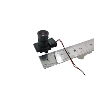
Buyers evaluating this reference platform can review the automotive night vision camera for motorcycle. Keeping detailed commercial specifications on the product page allows this article to remain focused on system design and validation.
Why HDR Matters Around Headlights and Streetlights
Motorcycle night scenes often contain bright headlights, reflective signs and dark road areas in the same frame. A conventional exposure may preserve the headlights while losing shadow detail, or reveal the road while clipping bright regions.
HDR is intended to retain more information across bright and dark regions, but HDR is not automatically equivalent to better night vision. Poorly selected exposure ratios, motion between exposures or aggressive tone mapping may produce artifacts, halos or an unnatural-looking image.
Test approaching headlights at multiple distances and angles.
Check whether dark road edges remain visible without excessive noise.
Evaluate reflective traffic signs and wet pavement.
Check fast transitions between tunnels, streetlights and open roads.
Validate LED traffic lights and signs for flicker or missing segments.
If HDR is a mandatory requirement, evaluate it as a defined sensor-and-ISP function. CK Vision’s automotive HDR camera module provides a separate starting point for projects with strong high-contrast requirements.
AHD Transmission and End-to-End Latency
AHD can carry HD video over a cable, but the interface name alone does not specify the delay visible to the rider. End-to-end latency is the combined result of image capture, processing, transmission, decoding and display refresh.
| Latency source | What affects it | What to validate |
|---|---|---|
| Sensor exposure | Exposure time and frame period, especially under low light | Motion blur and delay under actual night illumination |
| Sensor readout and ISP | HDR, noise reduction, frame buffering and image enhancement | Processing delay with the final firmware configuration |
| AHD link and decoder | Cable quality, decoder architecture and format conversion | Signal stability and decoder delay across cable lengths |
| Display pipeline | Scaling, frame buffering, overlays and panel refresh | Motion-to-photon delay on the production display |
Waterproofing Is a System-Level Requirement
A waterproof housing does not automatically create a waterproof installed system. Water may enter through the lens window interface, housing seam, cable gland, connector or damaged cable jacket. Temperature cycling can also create internal condensation even when liquid water does not visibly penetrate the enclosure.
Define the required ingress-protection level, test method, duration and post-test acceptance criteria in the project specification. Do not rely on the word “waterproof” without a project-specific test report covering the final cable and connector configuration.
Power, Grounding and Electromagnetic Compatibility
A motorcycle electrical system is not the same as a regulated laboratory power supply. Cranking, charging behavior, load switching, ignition noise, ground offsets and cable routing may disturb the camera or AHD signal.
Define the operating, cranking and abnormal-voltage conditions of the target motorcycle.
Confirm whether the camera receives regulated 5V, 12V or another protected supply.
Review reverse-polarity, overvoltage and transient-protection requirements.
Route video cables away from ignition and high-current wiring where possible.
Evaluate grounding, shielding and connector termination as one system.
Test for video noise, loss of synchronization, reset events and permanent damage.
For road-vehicle programs, the customer’s compliance team should identify the regulations and test standards applicable to the target market. UNECE Regulation No. 10 addresses vehicle electromagnetic compatibility, but applicability and approval scope must be confirmed for the final product: UNECE Regulation No. 10.
Vibration, Shock and Mechanical Stability
Motorcycle cameras can experience continuous engine vibration, road shock and mounting resonance. These stresses may loosen connectors, alter the lens position, damage solder joints or create visible image shake.
| Risk | Possible symptom | Inspection point |
|---|---|---|
| Mount resonance | Severe image shake within a particular RPM range | Mount stiffness, mass and isolation design |
| Lens movement | Focus shift or changed field of view | Lens retention and post-test optical measurement |
| Connector fretting | Intermittent video, noise or power interruption | Terminal retention, strain relief and contact condition |
| Seal degradation | Water entry after mechanical testing | Repeat ingress testing after vibration and shock |
The validation profile should represent the target engine, mounting location, road environment and expected service life. A test performed on a different bracket or a stationary bench cannot fully represent the final installation.
Day-to-Night Transition and Display Usability
Night performance is not limited to the darkest scene. The camera must also respond smoothly when entering a tunnel, passing under streetlights, facing oncoming headlights or returning to daylight.
Auto exposure: Check recovery time, visible stepping and sudden brightness changes.
White balance: Evaluate LED, halogen, sodium-vapor and mixed lighting.
Noise reduction: Confirm that moving objects are not blurred or followed by ghost trails.
Display brightness: Ensure the display remains readable without creating excessive rider glare.
Overlays: Measure latency again when guidelines, warnings or other graphics are enabled.
Image-quality acceptance should use representative video sequences and measurable criteria. A single still frame does not reveal exposure pumping, temporal noise, flicker or delayed recovery.
Prototype Validation Matrix
| Test condition | Measure or inspect | Project acceptance criterion |
|---|---|---|
| Unlit road | Road detail, noise, blur and object visibility | Define the target object and recognition distance |
| Oncoming headlights | Highlight clipping, flare and dark-area retention | Define acceptable clipping and visible road zones |
| Tunnel transition | Exposure recovery time and brightness steps | Set maximum recovery time and artifact limits |
| Wet road and rain | Reflections, lens-window droplets and signal stability | Define visibility and post-test ingress requirements |
| Engine RPM sweep | Image shake, connector stability and video interruption | No unacceptable blur, interruption or mechanical change |
| Electrical disturbance | Reset, sync loss, video noise and damage | Define functional status during and after each disturbance |
| End-to-end latency | Motion-to-photon delay across operating modes | Set the maximum permitted delay for the intended function |
Information Required Before Building an OEM Sample
A useful prototype request should describe the target motorcycle and system architecture, not only the desired resolution.
Target motorcycle platform and camera function
Front, rear, side or rider-monitoring position
Available mounting area and enclosure drawing
Required horizontal, vertical and diagonal field of view
Target object distance and display size
Required resolution, frame rate and AHD format
Cable length, routing and connector definition
Available power supply and electrical test requirements
Low-light, HDR or IR illumination requirements
Operating temperature, ingress and vibration requirements
Target-market compliance and documentation requirements
Prototype quantity and expected production volume
Developers comparing other vehicle-camera architectures can also review CK Vision’s automotive camera solutions.
Frequently Asked Questions
Is a low-light motorcycle camera the same as an infrared or thermal camera?
No. A visible low-light camera uses available visible light. An infrared system normally requires compatible spectral response and IR illumination, while a thermal camera detects long-wave infrared energy associated with temperature.
Does a 0.001-lux specification guarantee a clear road image?
No. Lux values depend on the measurement method, lens aperture, exposure, frame rate and acceptable image-quality threshold. Verify the complete camera on the target road and display.
Is 1080p sufficient for a motorcycle camera system?
It may be sufficient when the field of view, object distance and display resolution are properly matched. The decision should be based on pixels available across the target object, not resolution alone.
Does AHD automatically provide zero-latency video?
No. Sensor exposure, ISP processing, decoder behavior, scaling and display buffering all contribute to end-to-end delay. Measure motion-to-photon latency with the final hardware and software.
Is a waterproof camera housing enough for motorcycle use?
Not by itself. The optical window, housing seam, cable entry, connector, mating connector and condensation behavior must be tested as a complete installed assembly.
Can a 5V or 12V camera be connected directly to the motorcycle supply?
Only after electrical review. The design may require voltage regulation and protection against reverse polarity, transients, cranking conditions and electrical noise.
What should be provided for a customized sample?
Provide the motorcycle platform, installation drawing, viewing zone, FOV, cable and connector, display or decoder, power conditions, environmental requirements, target compliance standards and expected production quantity.
Final Engineering Recommendation
A motorcycle night-vision design should be approved as a complete system. Begin with the required viewing zone, then select the sensor, lens and placement. After that, validate exposure behavior, HDR, AHD transmission, total latency, display usability, sealing, electrical robustness and vibration on the target motorcycle.
This process produces a more reliable result than selecting a camera from one headline specification. It also makes prototype failures easier to diagnose because every performance requirement has a defined test condition and acceptance criterion.
Discuss Your Motorcycle Camera Project
Send CK Vision your installation drawing, viewing-distance requirement, AHD decoder, cable definition, power conditions and environmental test requirements for an initial compatibility review.
Contact CK Vision