Selecting a USB 3.0 camera module for machine vision or robotics requires more than comparing resolution and frame rate. The camera must capture the required detail, control motion blur, transfer image data reliably, fit inside the available enclosure and operate with the target host system.
A camera that performs well during a short desktop test may behave differently after it is installed near motors, connected through a longer cable or operated continuously inside a compact robot. Lighting, shutter type, exposure time, USB controller performance and host processing capacity can all affect the final result.
This guide explains how to evaluate resolution, frame rate, shutter type, video format, latency, lens, cable length and software compatibility when selecting a USB 3.0 camera for industrial vision and robotic systems.
What Is a USB 3.0 Camera Module?
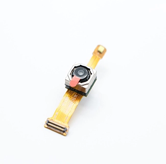
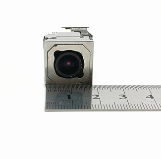
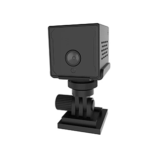
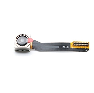
A USB 3.0 camera module is an embedded imaging board that transfers image data to a host system through a high-bandwidth USB interface. A complete module normally includes an image sensor, lens, image-processing or bridge controller, PCB or FPC, firmware, USB connector and cable.
Compared with USB 2.0, USB 3.x provides more available data bandwidth for higher-resolution, higher-frame-rate or less-compressed video. According to the USB-IF USB 3.2 specification overview, the current USB 3.2 family includes 5Gbps, 10Gbps and 20Gbps transfer-rate modes. In many camera projects, the term “USB 3.0” is still commonly used to describe the original 5Gbps interface.
USB 3.0 does not automatically guarantee a specific camera frame rate. Actual performance also depends on the image sensor, bridge controller, firmware, pixel format, cable, host controller and application software.
CK Vision’s USB 3.0 camera module uses the PS5268 sensor and provides 1920 × 1080 MJPEG output at up to 30 fps. The lens, PCB or FPC, field of view, cable and connector can be evaluated according to the target machine vision or robotic application.
Why Use USB 3.0 for Machine Vision and Robotics?
Machine vision and robotics systems often need to transfer more image data than general video-monitoring devices. The camera may need to capture small defects, read labels, identify parts, locate objects or provide visual input for navigation and robotic control.
USB 3.0 can be useful when a project requires:
Higher-resolution image capture;
Higher frame rates at lower resolutions;
Less-compressed or uncompressed image output;
Lower dependence on heavy host-side video decoding;
Multiple cameras connected to the same system;
Faster transfer of image data to an AI or vision application;
A detachable camera connection instead of a short MIPI interface.
However, USB 3.0 should be treated as one part of the complete imaging pipeline. A fast interface cannot compensate for an unsuitable sensor, excessive exposure time, poor lighting or insufficient host processing.
Start with the Imaging Task
Before selecting a camera, define what the vision system must detect, measure or recognize. Different tasks place different demands on the sensor, lens and interface.
| Vision Task | Important Camera Requirement | Questions to Ask |
|---|---|---|
| Presence or absence detection | Stable contrast and sufficient field of view | Does the system only need to confirm whether an object is present? |
| Barcode or label reading | Pixels on target, focus and motion control | What is the smallest character or barcode element? |
| Surface-defect inspection | High detail, controlled lighting and low noise | How small is the defect that must be detected? |
| Robotic positioning | Low latency, stable geometry and reliable frame delivery | How quickly must the robot react to each image? |
| Object classification | Consistent image quality and sufficient resolution | What image size does the AI model require? |
| High-speed motion analysis | Short exposure, high frame rate and suitable shutter | How fast does the target move across the image? |
| Dimensional measurement | Low distortion, calibration stability and controlled focus | What measurement accuracy is required? |
Defining the task first prevents the project from selecting an unnecessarily expensive camera or choosing a high-resolution module that cannot capture moving targets clearly.
Choose Resolution Based on Pixels on Target
Resolution should be selected according to the amount of detail that must appear on the target object. A higher megapixel count provides more pixels, but it also increases bandwidth, processing, memory and storage requirements.
For example, a 2MP camera may be sufficient for robotic navigation, general assembly verification and object-presence detection. A 5MP or 4K camera may be more suitable when the system must read small text, inspect fine surface features or crop a limited area from a larger image.
| Resolution | Typical Application | Main Trade-Off |
|---|---|---|
| 640 × 480 | Basic navigation, object presence and low-data embedded systems | Limited fine detail |
| 1280 × 720 | General robotic monitoring and basic recognition | Moderate image detail |
| 1920 × 1080 | Industrial monitoring, robotic vision and assembly inspection | Balanced detail and bandwidth |
| 2592 × 1944 | Document capture, labels and higher-detail inspection | Greater processing and bandwidth requirements |
| 3840 × 2160 | Digital cropping, fine-feature inspection and high-detail AI vision | Higher bandwidth, decoding and storage demand |
Projects that require document, label or surface-detail capture can also evaluate a 5MP USB camera module. Applications that require more pixels for digital cropping or complex pattern recognition may need a 4K USB camera module.
Resolution Does Not Determine Motion Performance
A common mistake is to assume that a higher-resolution camera will capture moving objects more clearly. Motion blur is mainly affected by exposure time, object speed, lens magnification and lighting.
A 4K camera using a long exposure can produce a more blurred moving image than a 2MP camera using a short exposure. For conveyor inspection, robotic picking and rotating components, the camera must collect enough light during a short exposure period.
To reduce motion blur:
Use shorter exposure times;
Increase controlled illumination;
Select a suitable lens aperture;
Use a higher-sensitivity sensor when appropriate;
Reduce unnecessary gain;
Evaluate whether a global shutter is required;
Synchronize lighting with image capture when possible.
Global Shutter vs Rolling Shutter
The shutter type affects how the camera captures moving objects.
Rolling Shutter
A rolling-shutter sensor exposes different rows of the image at slightly different times. It can provide good image quality and cost efficiency for stationary or slow-moving scenes.
Rapid movement, vibration or camera rotation may create skew, bending or partial-exposure artifacts. Rolling shutter can still be suitable for many robotic and industrial applications when movement is controlled and exposure time is short.
Global Shutter
A global-shutter sensor exposes the full frame during the same capture interval. This generally makes it more suitable for high-speed conveyors, robotic arms, moving parts and measurement tasks where geometric consistency is important.
| Application Condition | Recommended Shutter Direction |
|---|---|
| Stationary document or component | Rolling shutter may be sufficient |
| Slow robotic movement | Rolling shutter with short exposure may be sufficient |
| Fast conveyor inspection | Evaluate a global-shutter sensor |
| Robotic arm moving during capture | Global shutter is generally preferable |
| Precision measurement | Global shutter or carefully validated rolling shutter |
| General monitoring | Rolling shutter is often practical |
The final decision should be based on real target speed, exposure time and image geometry rather than the shutter name alone.
How Much USB Bandwidth Does the Camera Need?
The required bandwidth depends on resolution, frame rate, bit depth and video format. Uncompressed formats require substantially more bandwidth than compressed MJPEG output.
A simplified uncompressed bandwidth estimate is:
Width × Height × Frames per Second × Bits per Pixel
For example, 1920 × 1080 at 30 fps in a 16-bit-per-pixel YUYV format requires approximately 995 Mbps before USB protocol overhead. This already exceeds the theoretical 480Mbps signaling rate of USB 2.0, which is one reason USB 3.0 is useful for higher-data-rate uncompressed video.
MJPEG compresses each image frame and reduces the required USB bandwidth. The actual data rate varies according to image content, compression settings and firmware.
| Video Requirement | Interface Consideration |
|---|---|
| 1080p at 30 fps MJPEG | May operate on USB 2.0 or USB 3.0, depending on the module |
| 1080p at 30 fps YUYV | USB 3.0 is generally more suitable |
| High frame rate at lower resolution | USB 3.0 may provide the required data throughput |
| 4K MJPEG | Depends on compression, frame rate and host decoding |
| Multiple cameras on one host | USB-controller and shared-bandwidth planning is required |
MJPEG vs YUYV for Machine Vision
The video format affects bandwidth, latency, image quality and host processing.
MJPEG
MJPEG compresses each frame before transmission. This reduces USB bandwidth and can make higher-resolution streaming more practical. The host must decode the compressed image before it can be displayed or processed.
MJPEG may be suitable for:
General embedded monitoring;
Smart terminals;
Image recording;
Applications where bandwidth is limited;
Systems with efficient hardware or software decoding.
YUYV
YUYV is an uncompressed video format. It requires more USB bandwidth but avoids JPEG compression artifacts and decoding stages.
YUYV may be preferred for:
Computer vision pipelines requiring consistent pixel data;
Surface or edge analysis;
Applications sensitive to compression artifacts;
Low-complexity image preprocessing;
Systems with sufficient USB and memory bandwidth.
| Comparison | MJPEG | YUYV |
|---|---|---|
| USB bandwidth | Lower | Higher |
| Host decoding | Required | Not required for decompression |
| Compression artifacts | Possible | No JPEG compression artifacts |
| High-resolution transmission | More practical on limited bandwidth | Requires greater interface bandwidth |
| Vision processing | Suitable after decoding | Useful when uncompressed pixel data is preferred |
Frame Rate: More Is Not Always Better
Frame rate should match the speed of the process and the required reaction time. A higher frame rate produces more images per second but increases bandwidth, processing and storage requirements.
| Frame Rate | Typical Use |
|---|---|
| 15 fps | Slow monitoring and periodic inspection |
| 30 fps | General machine vision, robotics and embedded video |
| 60 fps | Faster robotic movement and conveyor inspection |
| 120 fps or higher | High-speed analysis, subject to sensor and interface support |
A high nominal frame rate is useful only when the exposure time, lighting and host system can support it. If the scene is too dark, the camera may increase exposure time and reduce the effective ability to freeze motion.
Understand Camera Latency
Latency is the time between light reaching the sensor and the processed image becoming available to the robot or vision application.
Total latency can include:
Sensor exposure time;
Sensor readout time;
ISP processing;
Image compression;
USB buffering and transmission;
Host-driver buffering;
MJPEG decoding;
Application processing;
AI inference time.
USB 3.0 provides more bandwidth, but interface speed alone does not define end-to-end latency. A compressed camera with multiple internal buffers may have more latency than an uncompressed configuration, even when both use the same USB interface.
For time-sensitive robotics, request measured latency data under the required resolution, frame rate, video format, cable and host configuration.
Choose the Lens and Field of View
The lens determines how much of the scene is visible, how large the target appears and whether the required details are in focus.
Before selecting the lens, provide:
Camera-to-target distance;
Required visible width and height;
Smallest feature that must be detected;
Permitted optical distortion;
Required depth of field;
Available lens and enclosure height;
Whether focus distance changes during operation.
| Vision Requirement | Lens Direction |
|---|---|
| Large working area | Wider field of view |
| Small target detail | Narrower field of view or higher resolution |
| Dimensional measurement | Low-distortion lens and calibration |
| Changing target distance | Autofocus or sufficient depth of field |
| Fixed inspection distance | Calibrated fixed-focus lens |
| Low-light imaging | Suitable aperture, sensor and illumination |
A wider lens is not automatically better. It can reduce the number of pixels covering each object and may introduce greater edge distortion.
Plan the Lighting Before Finalizing the Camera
Consistent lighting is one of the most important parts of a machine vision system. The camera cannot recover detail that was never adequately illuminated.
Lighting selection may involve:
Ring lights for general front illumination;
Backlights for silhouette and edge measurement;
Bar lights for directional surface inspection;
Dome lighting for reflective objects;
Strobe lighting for short-exposure motion capture;
Infrared illumination for selected applications;
Polarizers to reduce reflection.
Exposure, gain and white balance should be tuned under the final light source. If a project requires consistent color or low-light performance, ISP tuning services can be used to optimize the image pipeline for the selected sensor, lens and illumination.
USB 3.0 Cable Length and Signal Integrity
USB 3.0 uses higher-frequency signaling than USB 2.0 and is more sensitive to cable quality, connector design, PCB routing and electromagnetic interference.
Potential problems include:
Intermittent camera disconnection;
Frame loss;
Reduced negotiated USB speed;
Unstable high-resolution streaming;
Voltage drop at the camera;
Interference from motors and switching power supplies.
When specifying the cable, confirm:
Total cable length;
Shielding construction;
Wire gauge;
Connector type;
Cable bend radius;
Movement or flexing during operation;
Nearby sources of electromagnetic noise;
Power available at the module end.
The camera should be tested with the final cable inside the complete machine or robot. A short laboratory cable may not reveal problems that occur in the actual installation.
Check the Host USB Controller
USB 3.0 performance depends on the host controller and system architecture. Multiple USB ports may share the same controller and available bandwidth.
Before connecting several cameras, confirm:
How many USB controllers are available;
Which physical ports share the same controller;
The bandwidth required by each camera;
Whether other high-data-rate devices share the bus;
The host CPU and memory bandwidth;
Whether hardware MJPEG decoding is available;
The application’s buffering behavior.
When multiple cameras are required, distributing them across independent USB controllers can be more effective than connecting every camera through one hub.
UVC Compatibility on Windows and Linux
Many USB camera modules use the USB Video Class standard. The official USB Video Class document set defines standardized video formats and camera-control structures for compatible USB devices.
On Linux, UVC cameras are commonly handled by the uvcvideo driver and accessed through V4L2. The Linux UVC driver documentation also explains how vendor-specific extension-unit controls can be mapped into V4L2 controls.
UVC compatibility can simplify integration, but the final host should still be tested for:
Supported resolutions;
Supported frame rates;
MJPEG and YUYV availability;
Exposure and gain control;
White-balance control;
Focus control;
Vendor-specific functions;
Continuous-stream stability.
Projects requiring custom USB controls, trigger functions or firmware adaptation may also need camera sensor driver and software support.
Hardware Trigger and Synchronization
Some machine vision systems need the camera to capture an image at a specific event, such as when a part reaches an inspection point or a robotic gripper enters a defined position.
Before requesting hardware trigger support, define:
Trigger voltage;
Rising-edge or falling-edge activation;
Required trigger delay;
Acceptable timing variation;
Whether a strobe output is required;
Single-frame or continuous-trigger mode;
Whether multiple cameras must be synchronized.
Hardware trigger support depends on the sensor, USB bridge, PCB and firmware. It should not be assumed from the USB 3.0 interface alone.
Mechanical Integration in Robots and Machines
The camera must fit mechanically as well as electrically. Check the complete module dimensions, not only the sensor or PCB width.
Mechanical evaluation should include:
PCB or FPC dimensions;
Lens and holder height;
Connector direction;
Cable exit and bend radius;
Mounting holes;
Heat dissipation;
Vibration;
Enclosure window position;
Protection against dust or moisture.
For OEM projects, a custom USB camera module can be designed with an adjusted PCB/FPC outline, cable, connector, lens and mounting structure.
Recommended Configurations for Common Applications
| Application | Recommended Camera Direction | Key Validation |
|---|---|---|
| Robotic navigation | 1080p, suitable FOV and stable frame delivery | Latency, distortion and host compatibility |
| Pick-and-place positioning | Short exposure and calibrated fixed-focus lens | Pixels on target and coordinate repeatability |
| Conveyor inspection | Global shutter or validated short-exposure configuration | Motion blur and trigger timing |
| Label and barcode reading | 2MP or 5MP with controlled lighting | Smallest text, working distance and focus |
| Surface-defect inspection | 5MP or 4K with low-noise imaging | Defect size and illumination geometry |
| AI object classification | Resolution matched to the AI model | Image consistency and inference latency |
| Compact mobile robot | Low-power module with custom PCB/FPC | Size, thermal load and cable routing |
| Multi-camera robot | USB 3.0 cameras distributed across host controllers | Total bus bandwidth and synchronization |
USB 3.0 Camera Selection Checklist
Define the smallest required feature. Specify the defect, character, edge or object that the system must detect.
Calculate the required resolution. Determine how many pixels must cover the target feature.
Measure the target speed. Use it to estimate the required exposure time, frame rate and shutter type.
Define the field of view and working distance. Select the lens only after these values are known.
Select the video format. Decide whether MJPEG compression is acceptable or YUYV is required.
Check total USB bandwidth. Include all cameras and other devices sharing the same controller.
Confirm latency requirements. Measure the complete sensor-to-application delay.
Validate cable and power. Test the final cable near motors and other electrical equipment.
Confirm UVC and software support. Test the exact Windows, Linux or embedded host.
Run samples in the final environment. Test real targets, lighting, movement, temperature and operating duration.
Common Mistakes When Choosing a USB 3.0 Camera
Choosing by Megapixels Alone
More pixels do not guarantee better inspection. Lens quality, lighting, focus, motion blur and image processing may have a greater effect on usable detail.
Assuming USB 3.0 Guarantees Low Latency
USB bandwidth is only one part of latency. Exposure, buffering, compression, decoding and AI processing must also be measured.
Ignoring the Shutter Type
A rolling-shutter camera may distort fast-moving objects even when it provides sufficient resolution and frame rate.
Using Long Exposure Instead of Better Lighting
Long exposure can brighten an image but may create motion blur. Industrial vision systems should use controlled lighting whenever possible.
Testing with the Wrong Cable
A camera tested with a short desktop cable may become unstable with the longer cable used in the final machine.
Connecting Multiple Cameras to One Controller
Several physical USB ports may share the same host controller. The combined bandwidth may exceed what the system can sustain.
Assuming Every UVC Function Is Standard
Resolution and basic controls may be standardized, but trigger functions, GPIO and advanced settings may require extension units or custom software.
Frequently Asked Questions
Is USB 3.0 required for a 1080p camera?
Not always. A 1080p MJPEG camera may operate through USB 2.0, depending on the frame rate and compression. USB 3.0 is more useful when the project requires uncompressed output, greater bandwidth, multiple cameras or higher frame rates.
Is USB 3.0 better than USB 2.0 for machine vision?
USB 3.0 provides more available bandwidth, but the better interface depends on resolution, format, latency, cable and host requirements. A properly configured USB 2.0 camera can still be suitable for lower-data-rate inspection.
Do I need a global-shutter USB camera for robotics?
Not every robot needs a global shutter. It is most valuable when the target or camera moves rapidly and geometric distortion cannot be accepted. Slow or stationary applications may use a rolling shutter with controlled exposure.
Is MJPEG suitable for computer vision?
MJPEG can be used for computer vision after the image is decoded. It reduces USB bandwidth but may introduce compression artifacts and decoding latency. Applications sensitive to pixel consistency may prefer an uncompressed format.
How long can a USB 3.0 camera cable be?
Reliable length depends on cable quality, shielding, connectors, data rate, power and the installation environment. The final cable should be validated with continuous streaming in the actual machine.
Can several USB 3.0 cameras connect to one computer?
Yes, but the total bandwidth and power must be planned. Multiple ports may share one host controller, so cameras may need to be distributed across independent controllers.
Does a UVC camera need a separate driver?
A standard UVC camera normally uses the operating system’s USB video driver. Custom trigger, GPIO or vendor-specific controls may still require extension-unit mapping, an SDK or dedicated application software.
What information should I provide when requesting a camera sample?
Provide the application, target size, working distance, field of view, resolution, frame rate, target speed, shutter preference, lighting, host system, cable length, available installation space and expected production quantity.
Conclusion
The best USB 3.0 camera module for machine vision or robotics is not necessarily the module with the highest resolution or frame rate. It is the camera that captures the required detail without unacceptable motion blur, transfers data reliably and integrates with the lens, lighting, host and mechanical system.
Resolution, shutter type, exposure, frame rate, video format, USB bandwidth and latency must be evaluated together. Cable quality, host-controller architecture and UVC software support should also be tested before the production specification is finalized.
For an engineering recommendation, send CK Vision the target application, object size, movement speed, working distance, field of view, resolution, frame rate, host platform, cable length and enclosure drawing. The sensor, lens, PCB/FPC, USB interface and firmware can then be evaluated according to the actual machine vision or robotic system.